Project 1
We will make a project for liqiuid level control using PID Controller In TIA Portal, make a Dashboard in Ignition SCADA, take the data in MY SQL to analyze it And simulate the whole enviroment in Factroy IO.
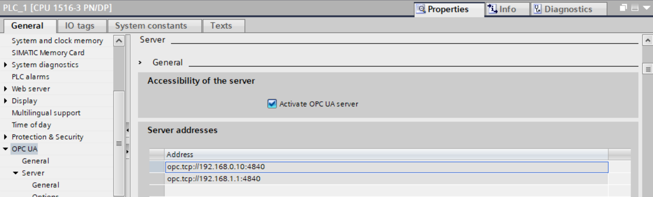
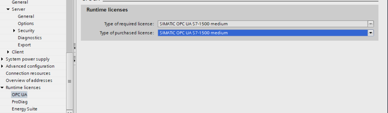
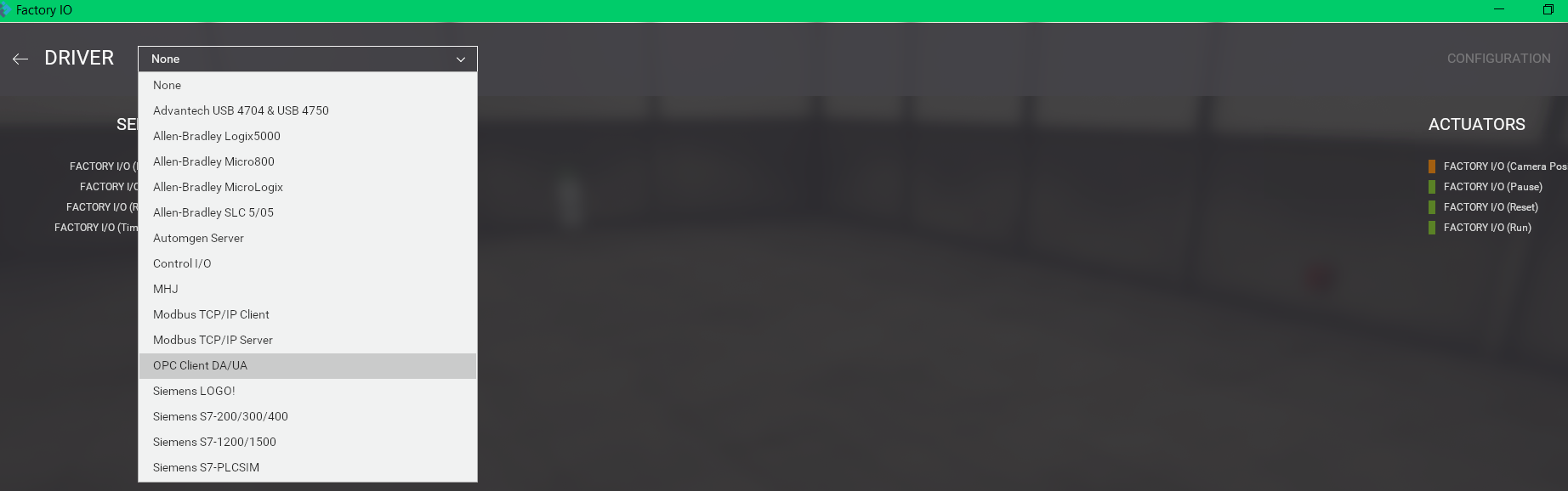
We will only use OPC UA Communication Protocol to cummunicate with Factory IO and Igniton SCADA
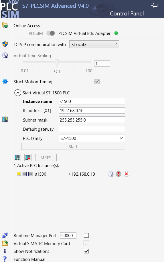
No REAL Hardware is Requird, we will simulate the PLC program in PLCsim Advanced
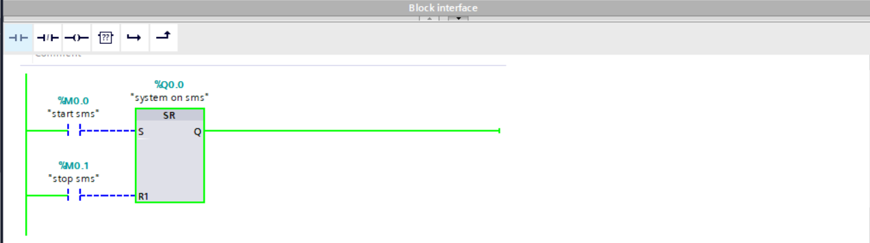
- Ladder Logic
- TIA Portal
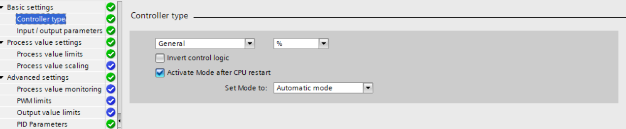
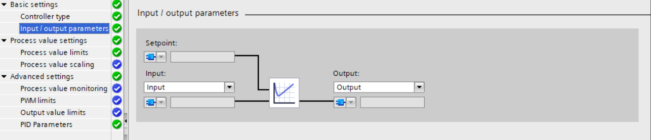
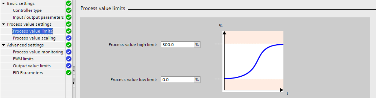
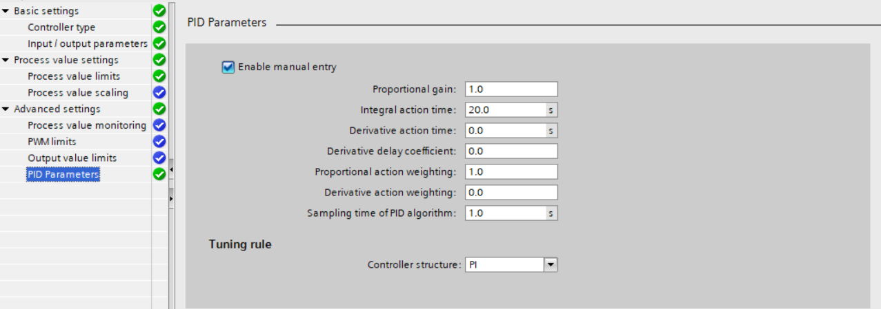
- PID Controller
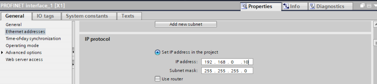
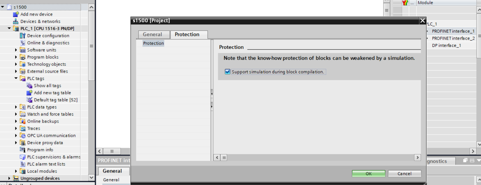
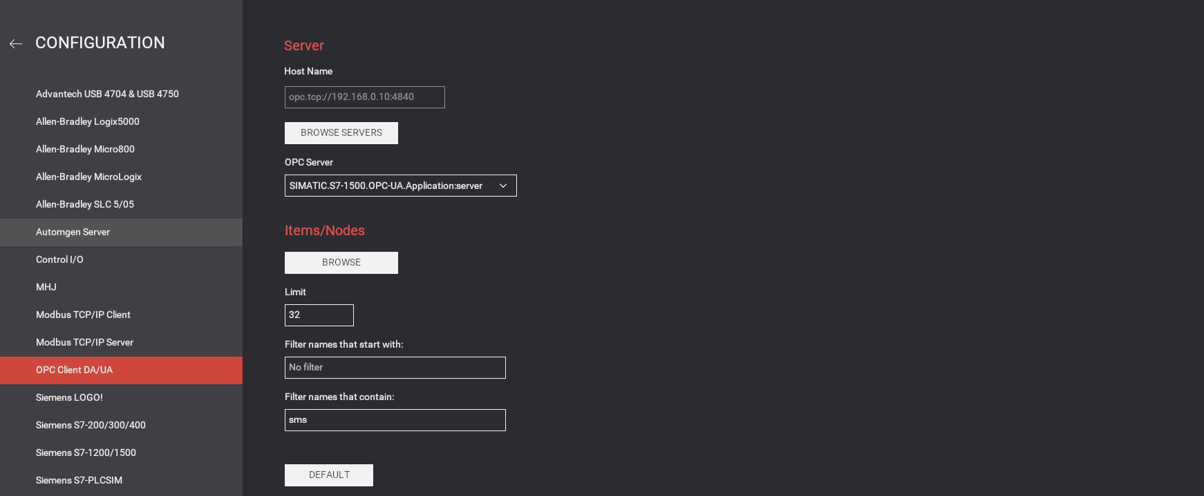
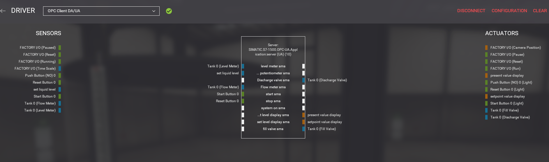
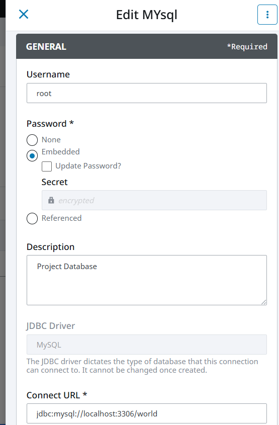
- Making OPC UA Connections
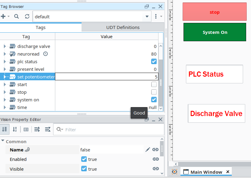
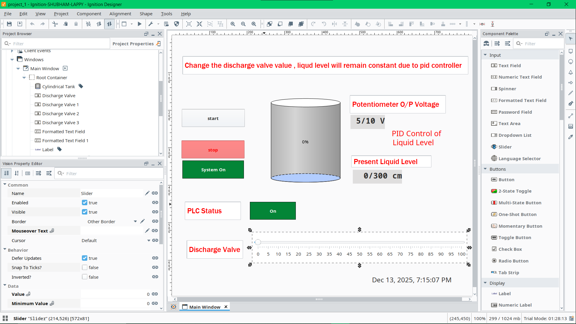
- Making Dashboard in Ignition SCADA
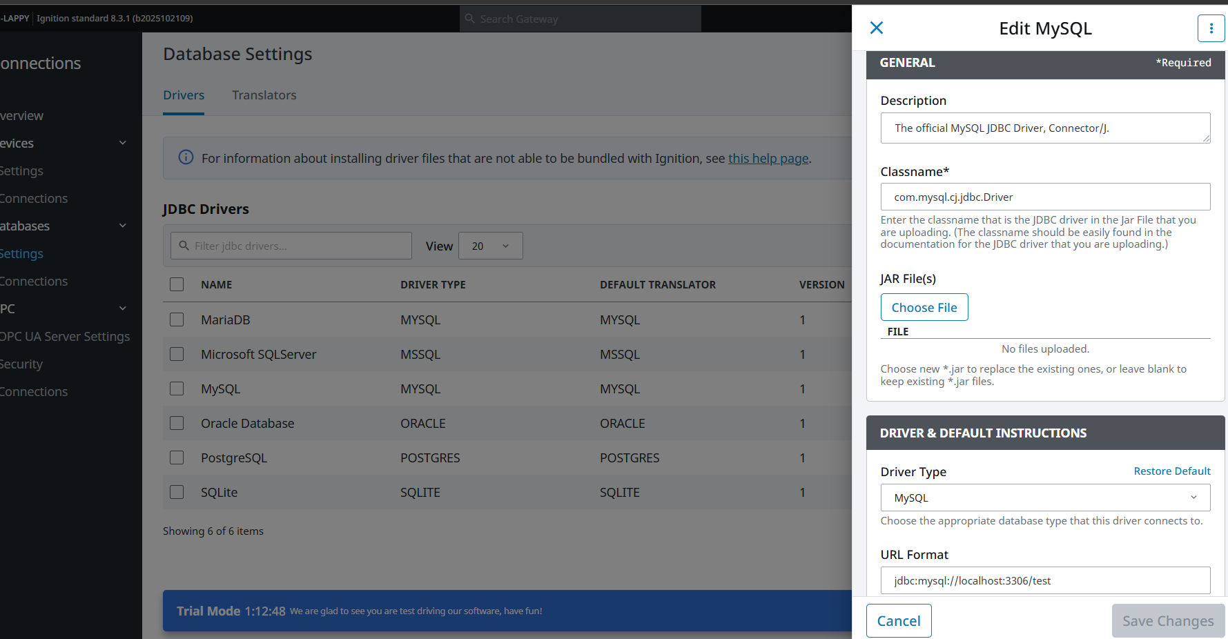
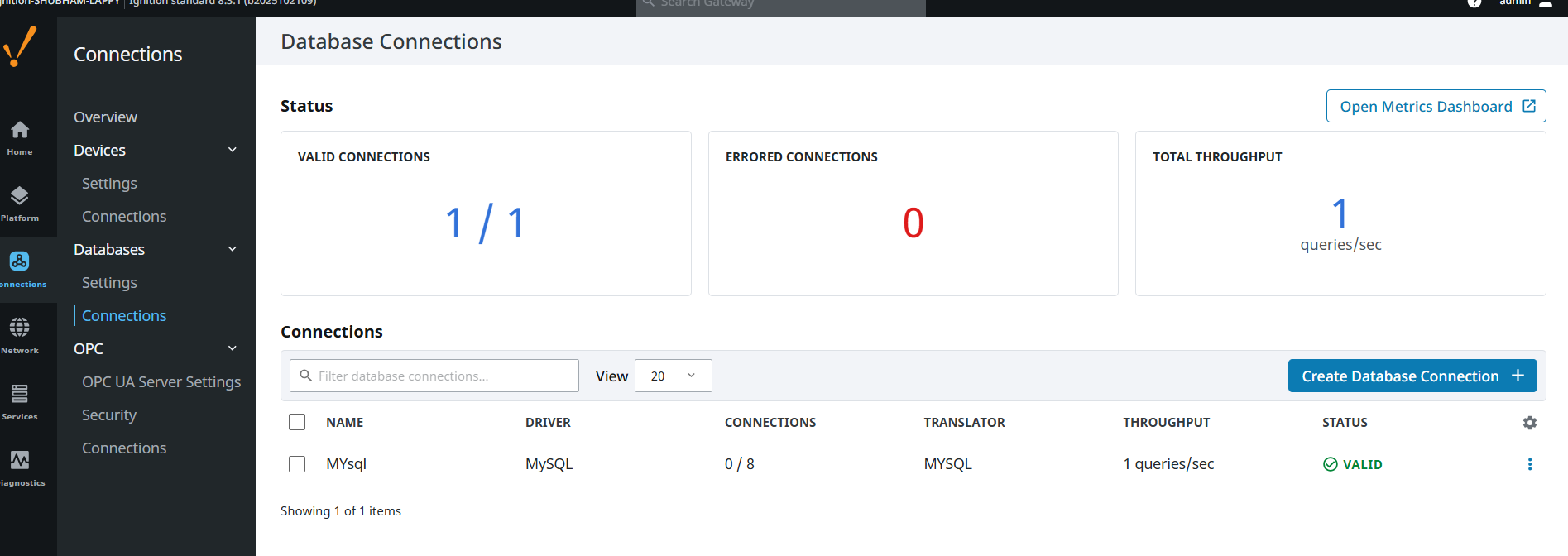
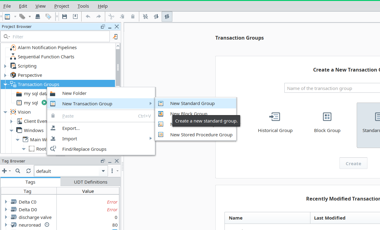
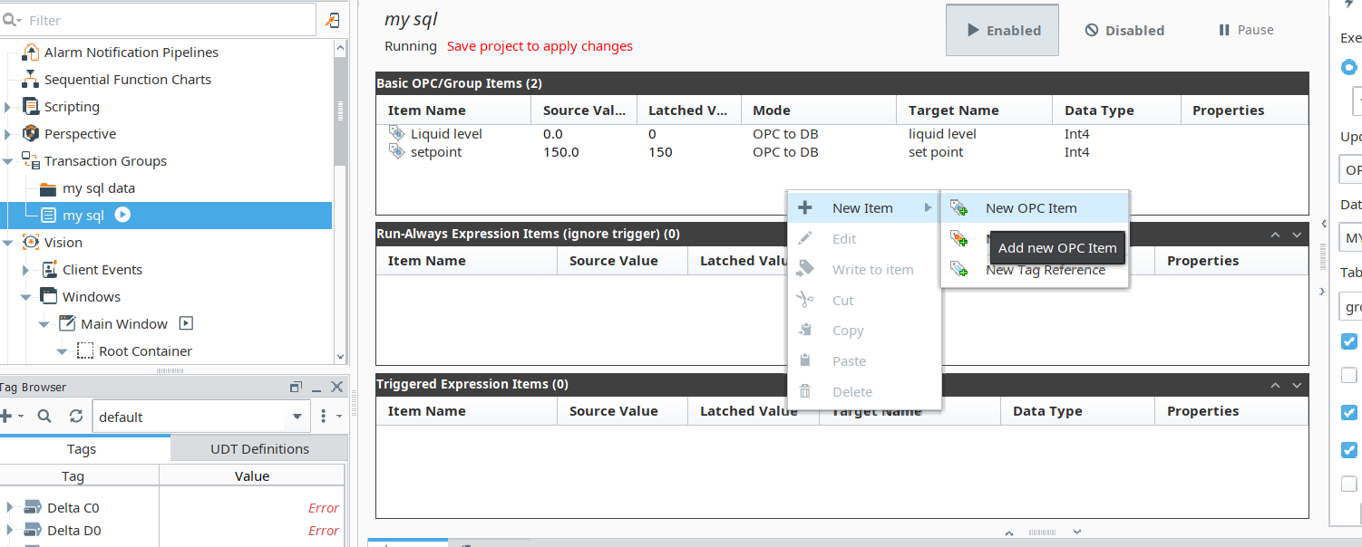
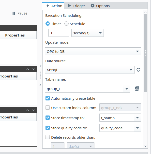
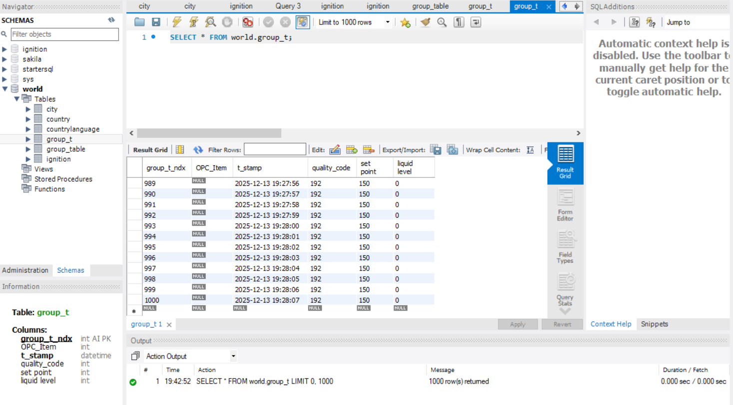
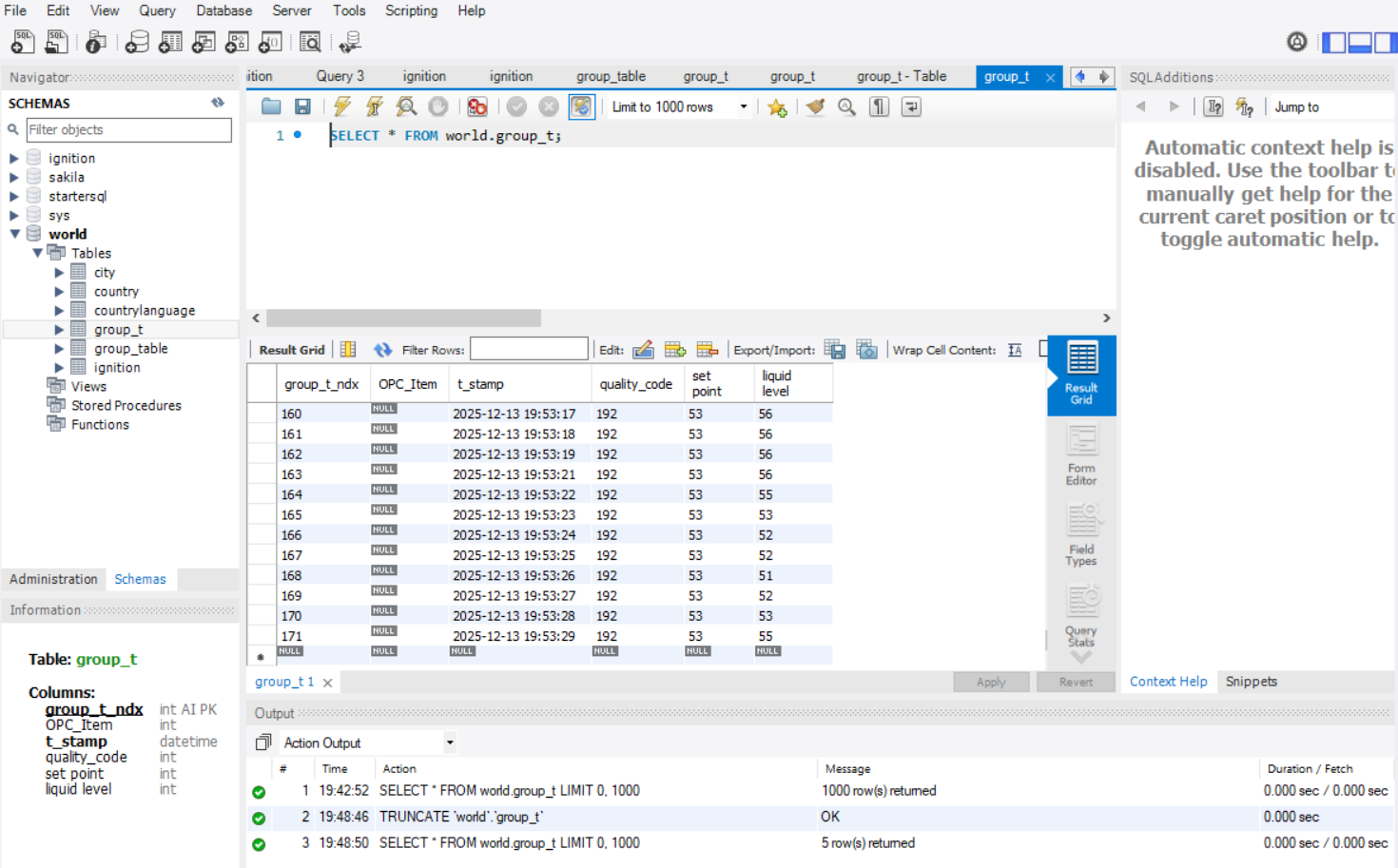
- Data Logging in MY SQL through Ignition
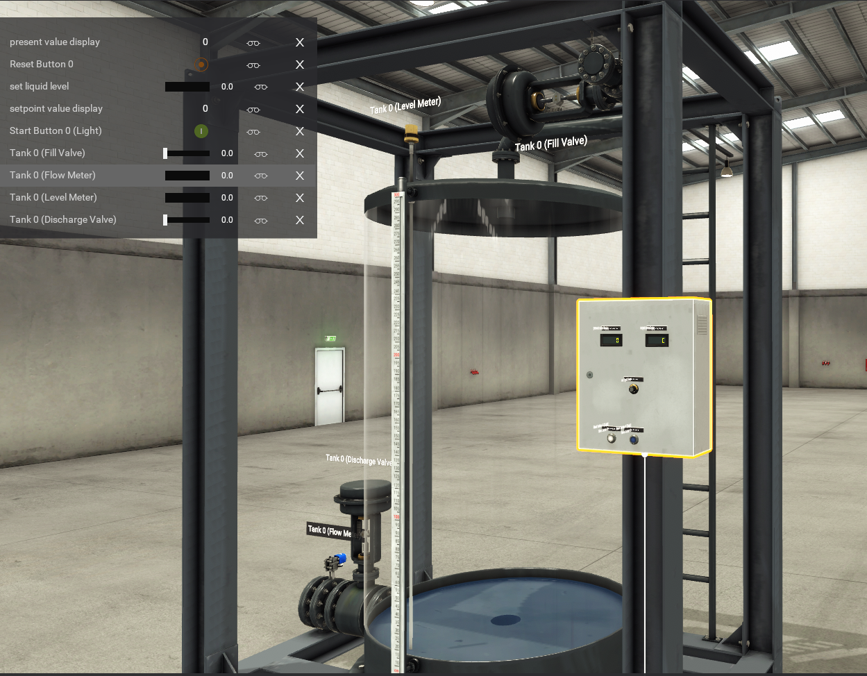
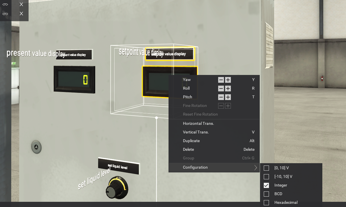
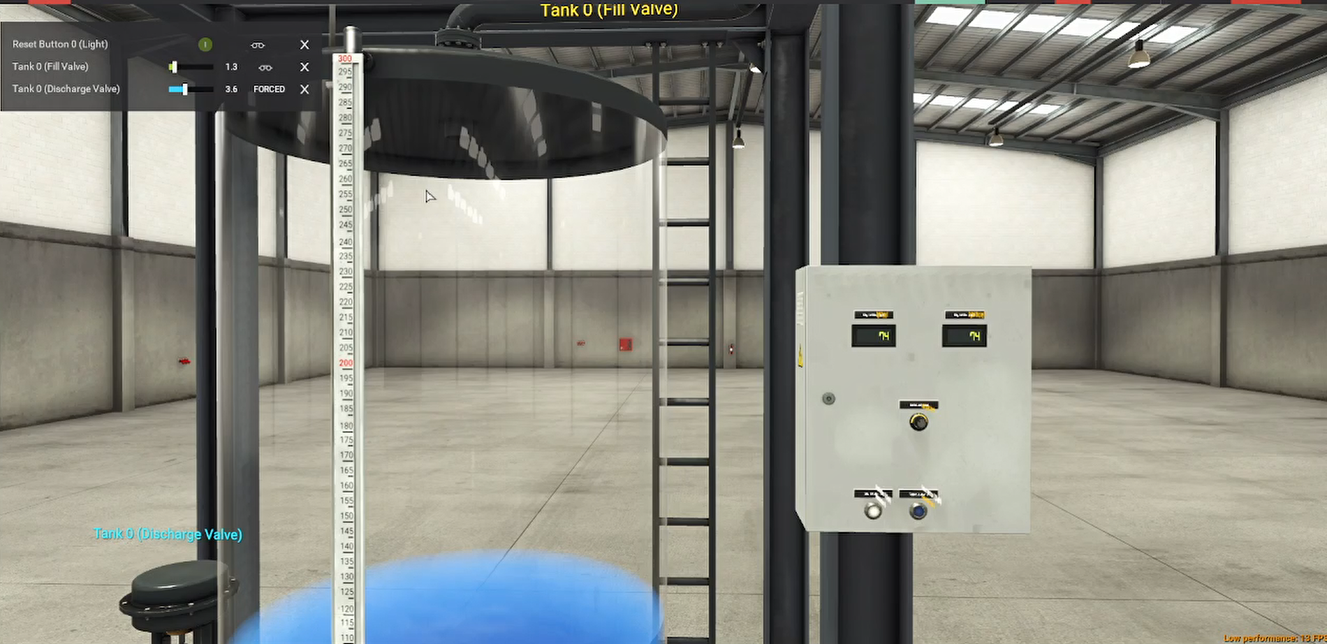
- Simulating Industrial Process in Factory IO
- Making Real Schematic Diagram for the Circuit Requird
Industrial Scenario: Maintaining Level in a Chemical Reactor (CSTR)
A Continuous Stirred-Tank Reactor (CSTR) is widely used in the chemical, pharmaceutical, and wastewater treatment industries.
1. The Challenge
The reactor's contents (reactants) need to be kept at a very precise and constant volume (level) to ensure a stable reaction rate, consistent product quality, and prevent the pump that feeds the next process step from running dry or the tank from overflowing.
| Component | Role |
| Controlled Variable (PV) | The actual liquid level inside the CSTR. |
| Setpoint (SP) | The desired liquid level. |
| Manipulated Variable (MV) | The opening/closing position of the outlet valve which controls the flow rate out of the tank. |
| Disturbance Variable | The inlet flow rate, which often fluctuates due to upstream processes. |
| Controller | The PID controller continuously calculates the required change in the outlet valve position. |
Why a PID Controller is Needed
Simple On/Off control (like a toilet float) is too aggressive and causes constant large swings (oscillations). A PID controller provides stability and precision:
P (Proportional): Provides an immediate, large response to a large error (level is far from the setpoint). For example, if the level suddenly rises, it immediately opens the outlet valve proportionally wider.
I (Integral): Eliminates steady-state error (the offset). If the level consistently settles slightly above the setpoint (P alone often can't eliminate this), the Integral action will slowly, but surely, continue to open the valve until the error is zero. This is crucial for precise level control.
D (Derivative): Provides a dampening action. It responds to the rate of change of the error. If the level is falling extremely fast, the D term will quickly close the valve a bit to prevent a rapid drop below the setpoint (overshoot or undershoot).
The Control Action
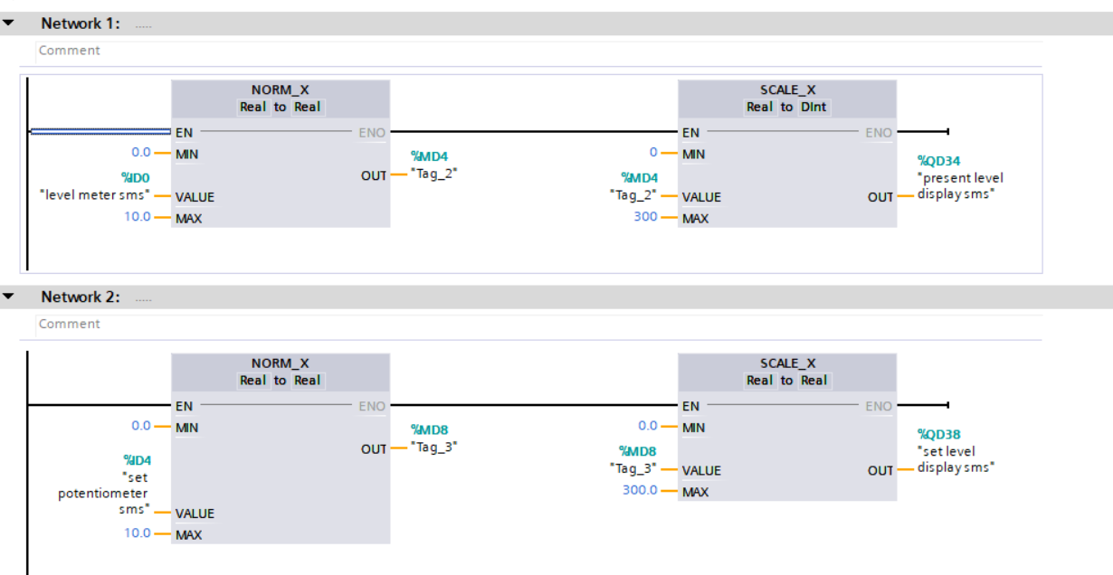
A Level Transmitter (sensor) continuously measures the current liquid level .7
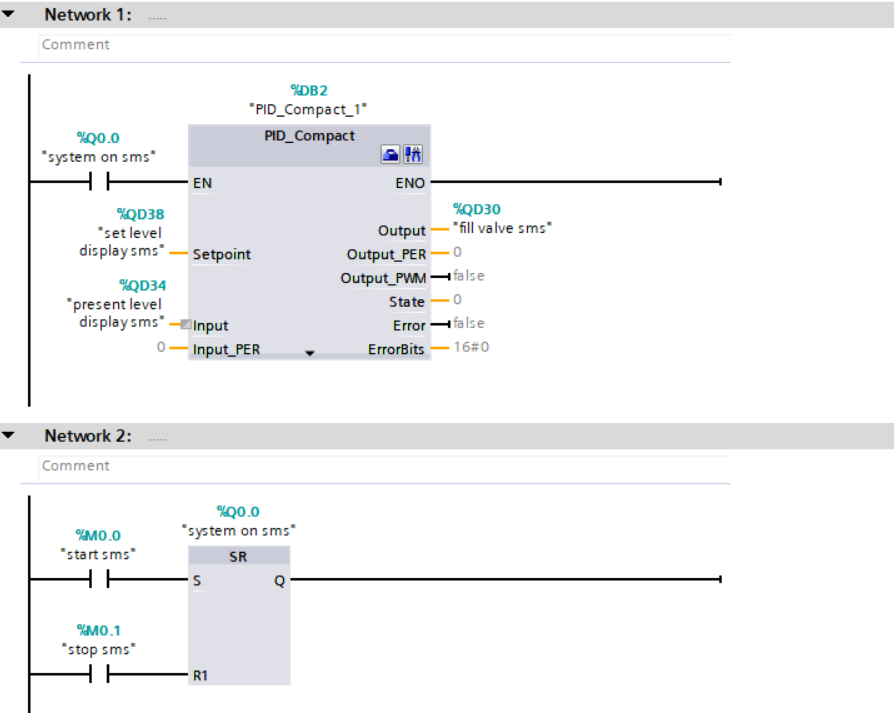
The PID controller calculates the error.
The controller calculates a new output value (the $MV$) based on the P, I, and D actions:
Softwares required for this project
- TIA Protal V16
- PLCSim Advanced V4
- Factory IO
- MY SQL
- Ignition SCADA
PC is also Important for simulating all of the above simultaniously, so i5 with SSD is enough, but i am simulating all of it in i3-6006U CPU and 8GB of RAM